Introduction
The objective of this Lesson is to review the important concepts in
fluid mechanics that underlay the development and analysis of stage
discharge relationships. The development of the governing equations and
relationships is based on
French's (1985) Open Channel
Hydraulics. It is assumed the reader has had an introduction to fluid
mechanics.
Introduction
Open channels are either artificial or natural. Natural channels include
creeks, estuaries, and streams and rivers. Artificial or open channels
include, for the purpose of our discussion, prismatic channels, canals,
and flumes. A constant bottom slope and
cross section are characteristic
of prismatic channels. Canals, in contrast, are long channels of mild
slope. Flumes are channels that are built above the ground to transport
water over depressions. Laboratory flumes are also used for basic
research.
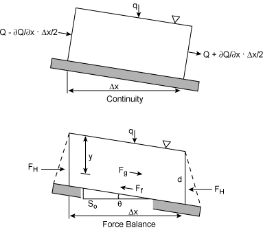
Figure 2.1 illustrates a reach of an open channel.
The depth of flow,
y, is the vertical distance from the minimum point of the channel
section to the water surface. The depth of flow measured perpendicular
to the channel bottom, d, is related
to y via the equation,
where θ is the channel slope.
For small θ, y
is approximately equal to d. The stage
of a river is the elevation of the water surface to a predefined datum.
Table 2.1 summarizes typical open channel flow cross sections. The
cross sections are classified according to the following parameters:
- cross sectional area, A
- wetted perimeter, P
- hydraulic radius, R
- top width, T
- hydraulic depth, D
- the section factor, Z
The cross sectional area is the area that is normal
to the direction of flow. The
wetted perimeter, P, is the total length of the line
representing the interface between the channel boundary and the fluid.
For a rectangular channel, the wetted perimeter is P=by/b+2y.
The hydraulic radius, R is
the ratio of the cross sectional
area to the wetted perimeter, R=A/P. The hydraulic radius
in a rectangular channel is R=by/b+2y.
The top width, T, of an open
channel is the width of the channel at the water surface. In
a rectangular channel, T=b.
The hydraulic depth, D is the ratio of the
cross sectional area to the top width, D=A/T.
The hydraulic depth is y in a rectangular channel.
Classification of Flows
There are a variety of criteria that are used to classify open channel
flow. If the flow is steady, this implies that the depth of flow is
unchanging in time. Unsteady flow is where the depth does vary in
time. From a mathematical perspective, if y is the depth of flow,
then ∂y/ ∂t=0 implies steady flow.
The flow regime may also be considered to be uniform or nonuniform.
Uniform flow does not vary with distance,
x; in other words,
∂y/ ∂x=0.
Nonuniform flow does vary with x.
Nonuniform flow can be further classified as being rapidly varied or
gradually varied, depending upon whether the flow depth changes rapidly
or slowly within a short distance.
The ratio of the flow's inertial to viscous forces also can be used to
classify a flow regime. The Reynold's number,
R, is the ratio of the
inertial to viscous forces,
where u is the average velocity of flow,
L, is a characteristic
length, and ν is the kinematic viscosity.
Laminar flow occurs when
the viscous forces dominate; the fluid particles behave in a coherent
fashion. Inertial forces dominate during turbulent flow.
Transitional
flow is an intermediate state; flow is neither laminar nor turbulent.
The characteristic length used with the Reynold's number is the
hydraulic radius, R. Laminar flow occurs when the hydraulic radius,
R is less than 500, e.g.
R < 500. The transitional flow regime
occurs in the range, 500 < R < 12,500. Turbulent flow
the Reynold's number exceeds 12,500.
Flow are also homogeneous or stratified. This has relevance in flow
systems in tidal environments (see Lesson 9)
or that have significant environmental contamination.
The flow is homogeneous provided the
density of the flow, or the density field, is constant throughout space.
Otherwise, the flow is stratified.
The degree of stratification is
indicated by the gradient Richardson number, Ri,
where g is the gravitational acceleration parameter,
ρ is the fluid density, and u
is the velocity. When Ri is large, the
stratification is stable. As Ri→ 0, the system is
homogeneous.
The Froude number, F, is
the ratio of the inertial to gravity forces. The Froude number can be expressed as
where u is a characteristic flow velocity, and L,
a characteristic length. The characteristic length associated with the
Froude number is the hydraulic depth, D.
An equilibrium situation occurs when F=1; the
inertial and gravitational forces are effectively in balance. When
gravitational forces predominate, F < 1, the flow is subcritical.
Inertial forces dominate in supercritical flow,
F > 1.
The denominator of the Froude number,
(gL)1/2,
is referred to as the celerity of an elementary gravity wave,
c=(gy)1/2. For subcritical flow, the
velocity of flow is less than c. As a result,
the wave can propagate upstream against the flow; importantly, the
upstream areas are in hydraulic "contact" with the downstream flow
environment. In supercritical flow, F > 1,
the flow velocity exceeds the celerity of the gravity wave. This wave
cannot propagate upstream.
The Continuity Equation
The principle of mass conservative requires that the difference between
the inflow and outflow in a river reach equal the time rate of change in
the volume of water in storage. Consider the one-dimensional, element
stream reach shown in Figure 2.1. The flow rate, Q, and the cross
sectional area, A, are known at the centroid of the reach. The
inflow, I, can then be expressed using a Taylor series as
|
I = [Q − |
∂Q
∂x
|
|
Δx
2
|
]Δt +qΔxΔt |
| 2.4 |
where q is the rate of lateral inflow per unit length of the reach.
Similarly the outflow, O is
The change in volume of water in storage is ∂A/ ∂tΔx Δt.
The continuity equation is then
Equation 2.6 may also be written as
|
u |
∂A
∂y
|
|
∂y
∂x
|
+u |
∂A
∂x
|
+A |
∂u
∂x
|
+ |
∂A
∂y
|
|
∂y
∂t
|
= q |
| 2.7 |
where u(x,t) is the mean x-velocity, and
y is the water depth in the reach.
For a rectangular channel where the width, B, is constant, the
Equation 2.7 can be expressed as
|
y |
∂u
∂x
|
+u |
∂y
∂x
|
+ |
∂y
∂t
|
= |
q
b
|
|
| 2.8 |
The three terms on the left hand side of the equation are known as the
prism storage, wedge storage, and rate of rise, respectively.
The Momentum Equation
The conservation of momentum equation is based on Newton's second law of
motion. As shown in Figure 2.1, there are three external forces acting
on the control volume. The gravity force, Fg, is the weight of the
fluid within the control volume that acts in the x direction,
|
Fg=ρg y Δx sinθ = ρg y Δx S0 |
|
2.9 |
where ρ is the fluid density,
g is the acceleration constant, y
is the elevation of the water surface above a datum, and θ is the
angle of the bottom channel with respect to the x axis. It is assumed
that, S0=sinθ.
The friction force, Ff, acts on the bottom and
sides of the control volume, or
where Sf is the friction slope or slope of the energy grade line.
Assuming hydrostatic conditions (the pressure linearly increases with
increasing depth) the pressure force on any vertical section, Fp,
can be expressed
Assuming Equation 2.11 is the pressure on the upstream face of the
control volume, the downstream pressure can be developed using a Taylor
series as,
|
Fp,downstream = Fp + |
∂
∂x
|
| [ |
1
2
|
ρg y2 | ]
|
Δx |
| 2.12 |
The difference or net hydrostatic pressure force,
Fpnet is then,
|
Fpnet=− |
∂
∂x
|
| [ |
1
2
|
ρg y2 | ]
|
Δx |
| 2.13 |
Newton's law equates the force, F, with the time rate of change in
momentum mu, or
where m is the fluid mass and
u is the flow velocity. The rate of
change in momentum can be expressed as
|
|
d (mu)
dt
|
= m |
du
dt
|
+u |
dm
dt
|
= ρA Δx |
dv
dt
|
+ρuqΔx |
| 2.15 |
In Equation 2.15, the derivative of the velocity with respect to time,
du/dt, is known as the total or material derivative.
Formally, it is expressed as,
Assuming the density of the fluid is constant and equating the
gravitational, friction, and pressure forces to the change in momentum
yields via Equations 2.10, 2.11, 2.13, and 2.16,
|
|
∂u
∂t
|
+u |
∂u
∂x
|
+ |
uq
A
|
+ |
g
A
|
y |
∂y
∂x
|
= g(S0−Sf) |
| 2.17 |
Equation 2.17 is the conservation of momentum equation for an open channel flow system.
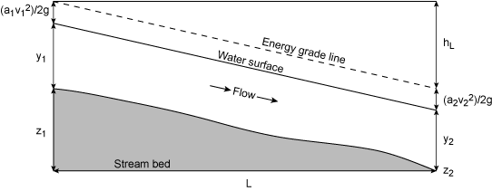
Conservation of Energy
From fluid mechanics, the total energy, H, of a fluid parcel
traveling at a constant speed (on a streamline) is the sum of the
pressure head, velocity head, and elevation head. The Bernouilli
energy equation can be expressed as
where p is the fluid pressure, and
γ is the specific weight of
the fluid. The first term in the
energy equation is the pressure head;
The second term is the velocity head;
u2 is
the velocity at point A.
The third term is the gravitational potential;
z is the elevation of the point above a datum.
The sum of the gravitational potential and the pressure potential is the
elevation of the hydraulic grade line above the datum.
Open channel flow is referred to as parallel flow provided
(1) minor fluctuations in turbulence are ignored, and (2) the streamlines have no
acceleration components over a cross section. The ramification of these
assumptions is a
hydrostatic pressure distribution; the sum of the
pressure and elevation heads is a constant and equal to the depth of
flow, y. The total energy can then be expressed as,
where α is a kinetic energy correction factor; it is necessary
for nonuniformity velocity profile. Equation 2.19 is valid provided
the channel slope is small, θ < 10°.
The kinetic energy correction factor, α, ranges from 1.05 to 1.36
in natural channels. It is a measure of the velocity distribution
across the channel. It is defined by the following equation,
where ui is the velocity over cross section
ΔA and u is the
average velocity over the entire cross section.
Figure 2.2 depicts the total energy variation in a stream reach.
Specific Energy
The specific energy of a fluid, E, is defined in terms of the
(hydrostatic) pressure head and velocity head as
For a wide rectangular channel, the specific energy can be expressed as
where b is the channel width and we have used the relation,
u=Q/A=Q/by.
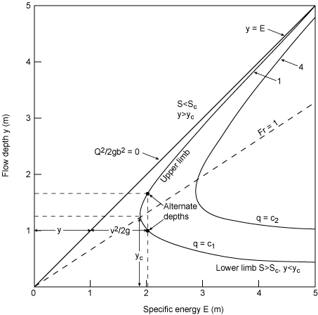
Figure 2.3 illustrates a typical specific energy diagram. For a given
specific energy and flow rate, there are two possible values of the flow
depth. These depths are called alternative depths.
The critical depth, yc,
is that depth that minimizes the specific energy or
|
|
dE
dy
|
= 1 − |
(Q/b)2
gy3
|
= 0 |
| 2.23 |
For a rectangular channel, the critical depth occurs at a Froude number
of 1. The upper curve in Figure 2.3 corresponds to flow that is slower
than critical; the flow is subcritical, F
< 1. Conversely, the lower curve exceeds the critical velocity and is
termed supercritical, F > 1.
Uniform Flow
Uniform flow occurs whenever the depth, the flow area, and the velocity
at every cross section are constant. Equivalently, the slope of the
energy grade line, water surface, and channel bottom are parallel.
Although these assumptions are rarely satisfied, uniform flow can occur
in long, straight, prismatic channels. In these open channels, the head
loss resulting from turbulent flow is counterbalanced by the decrease in
potential energy. The reduction in potential energy is the result of
the uniform decrease in the bottom channel elevation.
The average uniform flow velocity can be represented by the general equation,
where u is again the average velocity, R
is the hydraulic radius,
S0 is the channel slope, and
α and β are parameters.
Two variants of Equation 2.25 are used frequently in open channel
hydraulics. The first is the Chezy equation, which was developed in
1769. It can be expressed as
where C is known as the Chezy coefficient; it is known as a resistance
coefficient and has units of acceleration.
The second, is the Manning equation. Developed in 1889, the equation is
essentially empirical.
Manning's equation can be expressed as
where the parameter n is known as Manning's roughness coefficient; it
has dimensions of TL−1/3.
δ is a unit conversion factor.
δ = 1 corresponds to SI units;
for English units, δ = 1.49.
The flow rate, determined via Manning's equation, can be expressed as
The section factor is, by definition, AR2/3. The conveyance of the
channel, K, is
Gradually Varied Flow
The energy equation can be used to classify various types of gradually varied flow.
Assuming that α = 1 and
cosθ = 1, the energy equation is
Differentiating the energy equation yields
|
|
dH
dx
|
= |
d(u2/2g)
dx
|
+ |
dy
dx
|
+ |
dz
dx
|
|
| 2.31 |
dH/dx is the change in the total energy with
respect to downstream distance, x; it is known
as the friction slope, Sf, or
The third term in Equation 2.31, dz/dx is the variation in bottom
elevation of the channel with x, or
Finally using the relation, Q=uA, the velocity
head can be expressed as
where F is the Froude number. Combining the Equations produces
The variation in the depth of flow in a stream channel is a function of
S0, Sf, and the
square of the Froude number.
The classification of gradually varied flow is based on the following
assumptions (French, 1985):
- the overall head loss in a reach or channel section is the same as the head loss in the
reach with uniform flow with the same hydraulic radius and velocity. From Manning'
equation,
- the slope of the channel is such that the flow depth is the same whether measured
perpendicular to the bottom or vertically
- no air entrainment occurs
- α, the kinetic energy correction factor,
is constant in a channel
- the roughness coefficient is constant throughout the channel section and independent of
the depth of flow
The development of a general equation for the variation in water depth
begins by first rewriting the Froude number, F, in terms of the flow
rate, Q, and the top width, T, yields
Secondly, the Manning equation can also be expressed in terms of Q
and the wetted perimeter, P, as
Combining these equations with Equation 2.35 produces,
|
|
dy
dx
|
= |
S0−(n2Q2P4/3/δ2 A10/3)
1− (Q2T/gA3)
|
|
| 2.36 |
Recalling that the depth of flow under uniform flow conditions is termed
the normal depth, yn, and furthermore,
Sf=S0, the following
inequalities apply:
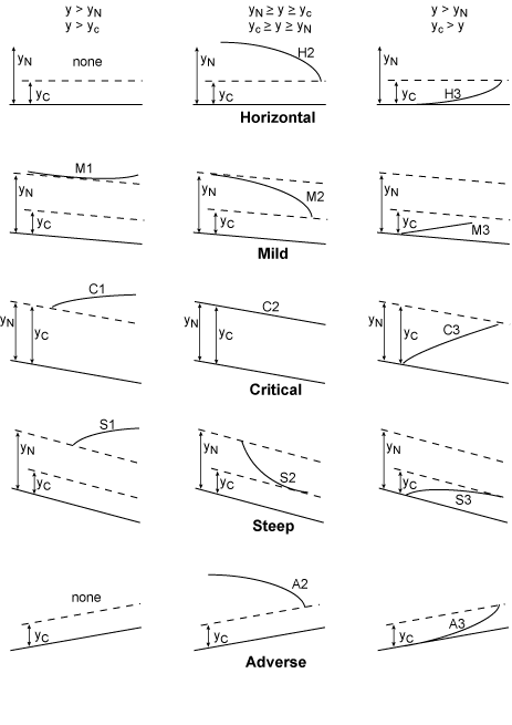
These set of inequalities divide a channel reach into three sections. Referring to Figure 2.4,
the cases are:
|
Case 1: y > yn > yc; S0 > Sf ; F < 1; dy/dx > 0 |
| 2.41 |
|
Case 2: yn > y > yc; S0 < Sf ; F < 1; dy/dx < 0 |
| 2.42 |
|
Case 3: yn > yc > y; S0 < Sf ; F > 1; dy/dx > 0 |
| 2.43 |
In each region, the sign of dy/dx determines the behavior of the
water surface. In Case 1, for example, at the
upstream boundary, y→
yn.
Since by definition Sf→
S0, dy/dx=0.
dy/dx→ S0 at the
downstream boundary since y→ infinity, and Sf
and F both approach zero. The water surface is designated as an M1 backwater
curve.
In case 2, the upstream boundary exhibits the same condition. At the
downstream boundary, however, y→ yc and
dy/dx→ infinity. This type of profile occurs either as a free
overfall or at a transition between a mild sloping channel and a channel
with a steep slope. The water surface profile is a M2 drawdown curve.
In case 3, both Sf and F→ infinity,
dy/dx is positive. At
the downstream boundary, y→
yc, dy/dx > 0 and the depth of
flow is increasing. The is a M3 profile; it occurs downstream of a
sluice gate in a mildly sloping channel or at the junction of a steeply
slope channel and mildly sloping channel.
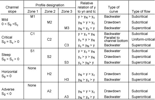
Table 2.2 summarizes the flow profile conditions in gradually varied
open channel flow.
Lesson 2 Summary
The objective of this lesson was to review the important concepts in
fluid mechanics that underlay the development and analysis of stage
discharge relationships. It is recognized that this material is theoretical.
However, a basic understanding of the concepts and definitions presented in this
lesson will facilitate the understanding of the remaining lessons
and future COMET hydrologic science modules.
The following terms and concepts were introduced in this lesson and
should be mastered prior to continuing with on to
Lesson 3.
Selecting a link in the list below will result in a jump to the
portion of the lesson material above that covered the relevant material
so that it can be reviewed as necessary.
Lesson 3 Preview
Flood forecasts require accurate and reliable
flow and stage measurement data at gaging stations.
The objective of Lesson 3 is
to address the hydrologic and hydraulic
considerations that impact the selection of a gaging station.
NWS hydrologist are not responsible for selecting gage sites, nor in
collecting stage or discharge data. However, the criteria used in
site selection and the hydraulic characteristics of the flow at the site, are important
considerations in understanding the limitations of the data,
and in providing insight into extrapolating
the streamflow data beyond historically observed conditions.
