

Introduction and Objective
Flood forecasts require accurate and reliable flow and stage measurement data at gaging stations. The selection of the location of a gaging station in a watershed is determined, in part, by the purpose of the streamflow record. Unfortunately, gaging station locations are rarely chosen based on the data requirements for forecasting models. In the design of a water resources system, gaging stations are located in the vicinity of the dams and reservoir of the project. In contrast, if a gaging station is to be sited as a part of a network of gaging stations, the siting criteria are predicated on obtaining the most reliable, cost effective hydrologic data. The data may be used to define the inventory of the basin's water resources and/or the assessment of long-range development plans.
The objective of this Lesson is to address the hydrologic and hydraulic considerations that impact the selection of a gaging station. The selection of a gaging site is based on obtaining the optimal hydraulic, hydrologic and economic conditions for the measurement of stage and discharge. NWS hydrologist are not responsible for selecting gage sites, nor in collecting stage or discharge data. However, the criteria used in site selection and the hydraulic characteristics of the flow at the site, are important considerations in understanding the limitations of the data, and in providing insight into extrapolating the streamflow data beyond historically observed conditions.
Gaging Station Selection
The selection of a specific gaging site ultimately reflects the ultimate use of the streamflow data. For example, if reservoir releases/outflows are to be monitored, the general location of the gaging station will be on a reach of a stream channel between the dam and the first confluence of a stream of significant size. There are tradeoffs involved in site selection even in this rather simple example. The station should obviously be located close to the reservoir, but should be far enough downstream of the discharge point such that the flow is uniformly established across the stream width. However, the gage should not be located so far downstream as to be impacted by a confluent stream.
From a purly hydrologic perspective, the general gage location is a reach of a channel between two confluent or tributary streams. Again the same consideration applies—the gage should be located far enough downstream from the upper tributary such that the flow is uniform across the channel width. The site should also be far enough upstream to avoid backwater effects.
The U.S. Geological Survey (Rantz et al., 1982) have developed nine criteria for an "ideal" gaging site. The criteria are:
- The stream course is straight for about 300 feet upstream and downstream of the gage site.
- At all stages, the total flow is confined to a single channel. There is also no subsurface or groundwater flow that bypasses the site.
- The streambed in the vicinity of the site is not subject to scour and fill. It is also free of aquatic plants.
- The banks of the stream channel are permanent. The are free of brush and high enough to contain floods.
- The stream channel has unchanging natural controls. These controls are bedrock outcrops or stable riffle for low flow conditions. During high flows, the controls are channel constrictions or a cascade or falls that is unsubmerged at all stages.
- At extremely low stages, a pool is present upstream from the site. This will ensure the recording of extremely low flows and avoid the high velocities associated with high streamflows.
- The gaging site is far enough removed from the confluence with another stream or from tidal effects to avoid any possible impacts on the measurement of stream stage.
- Within the proximity of the gage site, a reach for the measurement of discharge at all stages is available.
- The site is accessible for installation and operation and maintenance of the gaging site. The selection of a gaging site is again a compromise between these criteria.
The initial selection of a gaging site begins with the compilation of available hydrologic, geologic, and topographic data for the watershed. Stream reaches should be identified which have the following characteristics:
- straight alignment
- exposed consolidated rocks (as opposed to alluvium)
- stream banks subject to overflow
- steep banks for confined flow
- divided channels
- possible variable backwater impacts. These effects can be caused by tributaries, confluent streams, or reservoirs.
- potential sites for discharge measurement, e.g. current meter.
Stream reaches which satisfy some or all of these criteria will be given critical field examination and survey. The field survey will address the suitability of the site for both low and high flow regimes. For example, for low flow conditions, a stable, well-defined low water control is desired. If such a control does not exist, a feasibility study is conducted to evaluate artificial low-water controls. In streams with movable beds, e.g. sand channels, the siting of the gage is usually in a uniform section of a reach away from any channel obstructions. The impacts of aquatic growth also needs to be evaluated, especially the potential from backwater effects. Preliminary hydrologic assessment of the site should also identify the potential for subsurface discharge, especially in alluvial fans. Gaging stations should be located as far upstream as practicable in order to gage as much surface water as possible.
Similar considerations apply for high water stages. For example, historical high water marks are important in siting the elevation of the stage recording device. Also, historical evidence indicating deposition and scour of streambanks that have occurred during flood events should be identified. These data provide some indication of possible changes in the flow regime during future flood events.
An important consideration in the selection of a gaging site is the availability of adequate cross sections. The cross sections are used for the current-meter measurement of discharge. As will be explored in later lessons, theoretically the measurement cross-section should be of uniform depth; the flow lines should be parallel and uniform in velocity throughout the cross-section. Moreover, the measurement section should be in proximity to the gage to avoid the need for adjusting measured discharge as the storage varies, e.g. the stage changes rapidly during a discharge measurement. As recommended by the U.S. Geological Survey (Rantz et al., 1982), a distance of as much as 0.5 miles between the gaging site and measurement section is acceptable.
The possibility of backwater effects also has to be investigated whether from stream confluence or possible, downstream reservoirs. As a general rule, a gaging site should be the furthest upstream from the possible source of variable backwater. If this is not possible, it is necessary to identify a uniform reach for the measurement of slope as well as a site for the installation of an auxiliary gage. In a tidally influenced stream, unsteady flow will also required an auxiliary gage. This introduces another constraint on site selection, the availability of power. This is required to ensure the synchronized recording of stage at the two gages. Power requirements are also dictated by telemetering units necessary for flood forecasting and flood warning systems.
Cold regions present their own problems for gaging site selection. In regions with moderate ice buildup, desirable gage sites can be located,
- below an industrial plant. Waste heat and impurities in the water may actually lower the freezing point to the extent that open water conditions prevail
- immediately downstream from a dam with outlet gages. Since the density of water is at a maximum at 4° C, the water at the bottom of a reservoir is commonly near this temperature during the winter months. The outlet gates are typically located near the bottom of the reservoir. The released water is usually at this same temperature.
- on a long deep pool just upstream from a riffle. The weather must be extremely cold to completely cover the pool and riffle. The temperature of the stream bed, under ice cover, is generally slightly above freezing. Conduction and convection raise the water temperature slightly above freezing even though the water enters the pool at 0° (C). The temperature rise is usually sufficient to prevent ice formation.
Following the evaluation of these criteria and the identification of the tradeoffs between them, the sites for the recording stage gages and for the cableway for discharge measurements are selected. The field locations are identified and referenced. At each site, the maximum stage at which the low water control is effective should be determined. Moreover, the intakes of the stage recorder should be located upstream from the low water control—a distance of three times the depth of water on the control at the estimated maximum stage. If the intakes are closer to the control, the intakes may lie in an hydraulically undesirable region, i.e. the streamlines have vertical curvature.
Gaging Station Controls
The stage record is transformed or converted into streamflow using a stage-discharge relationship for the gaging station. The physical element that is responsible for the characteristics of the stage-discharge relationship is known as a control. Hydrologists differentiate between section and channel controls, natural and artificial controls, and complete, partial, and compound controls.
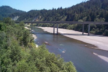 |
| Figure 3.1. Section control (riffle under the bridge) during low flow at Eel River near Scotia. |
 |
| Figure 3.2. Channel control during high flow at Eel River near Scotia. |
Section controls occur when the geometry of a single cross section just downstream of the gage constricts the channel. The constriction results from an increase in the stream bed as occurs at a natural riffle or rock outcrop, or at a constricted weir or dam. Constriction can also result from man made channel encroachment, e.g. a bridge where the waterway opening is considerably narrower than the width of the existing channel. Figure 3.1 illustrates a typical section control where the channel narrows though a riffle directly under the bridge.
In contrast, a channel control occurs when the roughness and geometry of a long reach of channel downstream of a gaging station control the stage—discharge relationship. Generally, the length of the stream channel responsible for the the "channel control" increases as the discharge rate increases. Relatively flat stream gradients, require longer channel control reaches. A channel control is shown in Figure 3.2.
Controls are also complete controls in the sense of governing the entire range of stage at a gaging station. This typically does not occur, and compound controls are used for the stage—discharge relationship. As illustrated in Figures 3.1 and 3.2 for the Eel River near Scotia, a section control is used as the control for low flow regimes; channel control, high stages. Compound control can sometimes include two section controls and a channel control. The channel control again is effective at high stages. A section control further downstream is "operational" for intermediate stages while upstream section control is used for low flow stages.
Also, a section control can be a complete control provided the section control is a weir, dam, cascade, or falls and the height is not submerged at high discharges. Similarly, a channel control can be "complete" if a section control is not available or in an artificial channel.
A partial control acts with another control in defining the stage-discharge relationship. This always occur when a compound control is used. For example, a common situation is when a section control is the only control for low stages; high stages are controlled by channel control. During intermediate stages, there is a transition from one control to the other. Submergence is "drowning out" the section control. Within the transition period, the two controls act simultaneously; both are considered as partial controls.
Attributes of Satisfactory Controls
As discussed by Rantz et al. (1982), a satisfactory control has two principal attributes: (1) permanence or stability and (2) sensitivity. Stability of the control implies the stage-discharge relationship will also be stable. Unstable controls required frequent discharge measurements for continual recalibration of the stage-discharge relationship. This diminishes the accuracy of the streamflow record and increases dramatically the operational costs of the gaging station.
Several factors influence the permanence of controls. The primary cause of variation is the high velocity associated with high discharge. If a control is a natural control such as a rock ledge outcrop, it is relatively unaffected by high velocities. Other natural controls such as gravel and sand bar riffles will likely shift. Sand channel sections are the most likely to change resulting from velocity induced deposition and scour.
Vegetal growth can also impact the control. Aquatic vegetation growth on section controls will increase the stage for a given discharge, nominally in the low flow range of conditions. Vegetal growth also impacts channel controls by reducing velocities and the effective waterway area.
The sensitivity of a control, especially for low flows, is related to the variation in discharge with stage changes. A small change in discharge should produce a significant change in stage. Typically a low flow control is sensitive if a change of no more than 2% of the total discharge is represented by a change of one unit of record stage.
Sensitivity of the gaging site at low flow usually requires that the width of flow at the control is severely restricted. This can occur if the control is notched, or if the cross section has a flat V shape or parabolic shape. These shapes ensure that a measureable change in stage occurs for small changes in discharge. For example, three channel cross sections are shown in Figure 3.3 below. A comparison of the stage-discharge relationship for the three channels at a constant flow velocity of 1 m/sec is illustrated in Figure 3.4. At low flow rates, the V shaped channel has greater measurement sensitivity since there is a much larger change in stage compared to the trapezoid and rectangular shaped channel.
 |
| Figure 3.3. V, trapezoid, and rectangular shaped stream channels. |
 |
| Figure 3.4. Stage - discharge relationship for V, trapezoid and rectangular shaped stream channels. |
Artificial Controls
From an economic perspective, the gaging site ideally should be located upstream from a suitable natural control. In the event that natural conditions do not provide the required sensitivity or stability, artificial controls are used to define the stage-discharge relationship. Artificial controls can also reduce the undesirable characteristics of natural controls. They are physically stable, and they are not subject to the cyclical growth of aquatic vegetation (algae excepted). They are also less likely to be affected by winter ice.
Formally, an artificial control, which is always a section control, is a structure built in a stream channel that constricts and stabilizes the channel. It simplifies the procedure of obtaining accurate discharge records. A typical artificial control is a broad-creasted weir; the weir is designed to conform to the height and shape of the streambed. Figure 3.5 depicts a broad-creased weir under construction and in operation.
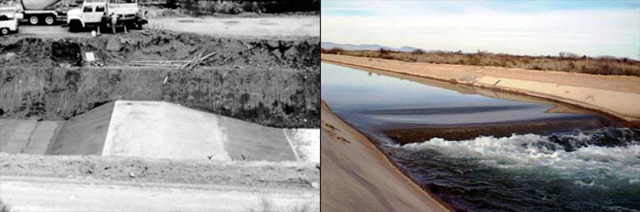 |
| Figure 3.5. Broad-creasted weir. |
In drains and canals where the range in discharge is limited, thin-plate or sharp-creasted weirs and flumes are commonly used artificial controls. The artificial controls are designed to function as complete controls throughout the entire range in stage. Thin-plate weirs, as shown in Figure 3.6, are used in channel where the streamflow is relatively sediment free; the stream banks also have to be high enough to incorporate the increase in backwater stage associated with the installation of the weir.
 |
| Figure 3.6. V notch weir. |
Flumes can be used in sediment laden channels primarily because there are largely self-cleaning. The principal advantage in canals and drains, however, is that they cause relatively little head loss. The capital cost of flumes is significantly greater than that of weirs.
Flumes are classified according to the flow region that principally controls the measured stage. Flumes are either critical-flow flumes or supercritical-flumes. The most widely used critical flow flume is the Parshall flume shown in Figure 3.7. Supercritical flumes are used in streams and rivers that transport heavy sediment loads. The most common flume, is the trapezoidal supercritical flow flume developed by the U.S. Geological Survey.
 |
| Figure 3.7. Parshall flume. |
Design Criteria for Artificial Controls
The design of artificial controls should be predicated on the following attributes:
- the control should be stable and permanent.
- the crest of the control should be as high as possible to minimize the effects of variable downstream conditions or to limit these effects to high stages only
- the profile of the crest of the control should be designed such that a small change in discharge at low stages produces a measurable change in stage. If the design is to be effective at all stages, the profile of the crest is designed so that the stage-discharge relationship can be extrapolated without serious error
- the control structure's shape is such that water passage does not create undesirable disturbances in the upstream or downstream channel.
- the control should be self-cleaning, especially in a sediment-laden environment.
- cost—the cost is affected primarily by the width of the stream and the condition of the bed and bank material. The width of stream controls the size of the structure. The bed and bank material dictate the type of construction that must be used to minimize subsurface discharge.
Weir and Flume Calibration Issues
Artificial controls are typically designed with laboratory rated or field rated weirs or flumes. The issues is whether to use the precalibrated rating or to calibrate the control in situ. In the United States, the conventional wisdom is that it is seldom desirable to accept the rating curve prepared for the model structure without checking the entire rating in the field. Field studies have demonstrated that there are differences between model and prototypes. The differences are sufficient such that complete on site calibration is required.
Lesson 3 Summary
Accurate and reliable flood forcasts require accurate and reliable flow and stage measurement data at gaging stations. The objective of this third lesson is to provide background information on the criteria used to select stream gaging stations, and on the different type of "controls" governing the hydraulics at the gage site. While NWS hydrologist are not responsible for selecting gage site, or in collecting stage or discharge data, understanding the criteria used and the hydraulic characteristics of the flow at the site can help in understanding the data limitiations and in providing guidance in extrapolating beyond the limits of previously observed data. The following terms and concepts were introduced in this lesson and should be mastered prior to continuing with on to Lesson 4. Selecting a link in the list below will result in a jump to the portion of the lesson material above that covered the relevant material so that it can be reviewed as necessary.
- Definitions
- Concepts
Lesson 3 Review Questions
- Gravel bar riffles make poor controls.
- For a control to be sensitive, a small change in flow should cause a LARGE/SMALL change in stage.
Lesson 4 Preview
Developing a stage-discharge relationship for a stream requires a set of observed stage (water depth) and discharge (flow) measurements. Lesson 4 provides an overview of the techniques and instruments used to measure water stage. The accuracy of the data and possible errors are also described.